
I’ve been wanting to connect to my CarPC volume control made by the incremental rotary encoder and plug in usb port. By turning the encoder to the left — the volume must decrease to the right — should be increased. Click down the encoder knob — mute volume.
An incremental rotary encoder provides cyclical outputs (only) when the encoder is rotated. They can be either mechanical or optical. The mechanical type requires debouncing and is typically used as digital potentiometers on equipment including consumer devices. Most modern home and car stereos use mechanical rotary encoders for volume control.

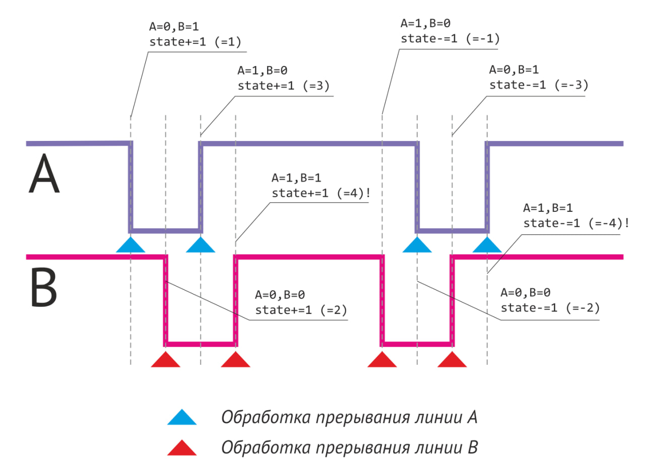
They employ two outputs called A & B, which are called quadrature outputs, as they are 90 degrees out of phase.
The state diagram:
Coding for
clockwise rotationPhase A B 1 0 0 2 0 1 3 1 1 4 1 0
Coding for
counter-clockwise rotationPhase A B 1 1 0 2 1 1 3 0 1 4 0 0
Two square waves in quadrature (clockwise rotation).
The two output wave forms are 90 degrees out of phase, which is all that the quadrature term means. These signals are decoded to produce a count up pulse or a count down pulse. For decoding in software, the A & B outputs are read by software, either via an interrupt on any edge or polling, and the above table is used to decode the direction. For example, if the last value was 00 and the current value is 01, the device has moved one half step in the clockwise direction. The mechanical types would be debounced first by requiring that the same (valid) value be read a certain number of times before recognizing a state change.
On encoders with detents there are different ways to switch states. In some, both A and B are always open circuit at the detents, and an entire 00 > 00 switching cycle occurs while transitioning from one detent to the next. Others have detents of alternating 00 and 11 value, with staggered switching times during the transition between detents.
If the encoder is turning too fast, an invalid transition may occur, such as 00 > 11. There is no way to know which way the encoder turned; if it was 00 > 01 > 11, or 00 > 10 > 11.
If the encoder is turning even faster, a backward count may occur. Example: consider the 00 > 01 > 11 > 10 transition (3 steps forward). If the encoder is turning too fast, the system might read only the 00 and then the 10, which yields a 00 > 10 transition (1 step backward).
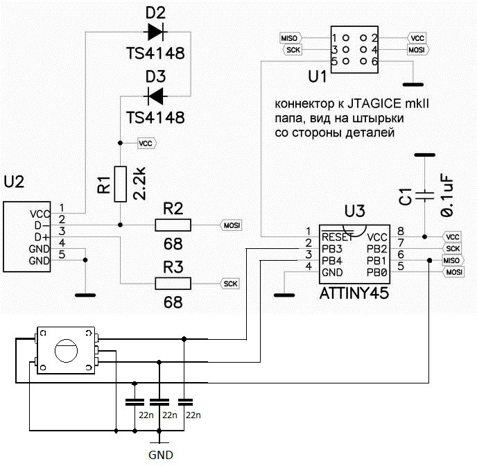
To implement the project I used two prototyping boards AVR-USB-MEGA16 & AVR-USB-TINY45 .


Connecting encoders to the prototyping boards is as the present at the circuits.

To make this device is determined by the operating system as consumer control with media keys was used corresponding USBHidReportDescriptor, taken from descriptor of USB multimedia keyboard, and was written the appropriate code to handle.
P.S.
ATMega32: FUSE_L = 0xCF, FUSE_H = 0x18, LOCKOPT BYTE: 0x3F.
ATTyny85: FUSE_L = 0xD1, FUSE_H = 0xDD
Examples of firmware are in source codes written by AVR Studio 5.0.
The source codes ver.2. You can increase the rate of change of the volume in the code specifying the variable AdditionalKeyPress.
The source codes ver.3. Solved problem — device is not detected by the OS after a reboot or turn off the computer, if it on MCU ATTyny45(85) without crystal.